
Grant Munro from Rotorsport Racing & Engine Balancing shows us exactly what goes on when balancing the internals of the rotary engine
When you think about the speed in rpm at which your engine internals are moving, both in a rotational and reciprocating (for piston engines) or eccentric (for rotary engines) motion, while you’re hard up the loud pedal, it’s somewhat mind-boggling to think they can see upwards, and sometimes in excess of, 10,000rpm, especially when we’re talking rotary engines. The balance of these components is integral to allowing these types of rpm and not have your engine completely destroy itself — think of a washing machine on fast spin, with a cinder block inside.
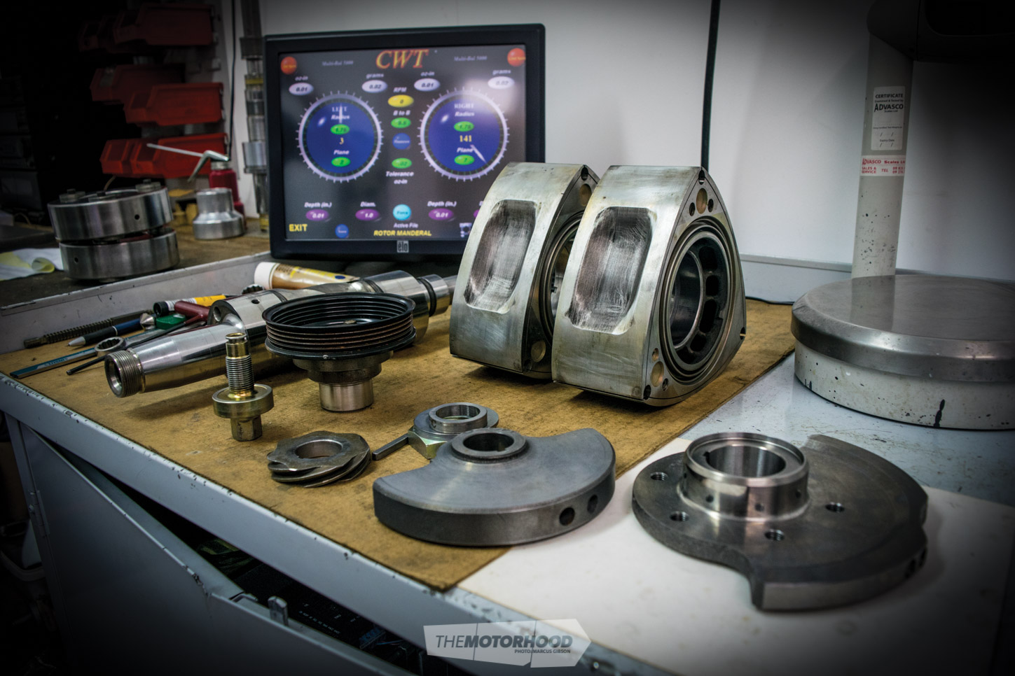
When dealing with high rpm, even the slightest variation in weight between any parts in the rotating assembly can cause vibrations. Any vibration in the engine is doing damage. So exactly how do you ensure your internals are balanced perfectly, and why should you have something balanced even if it’s from a factory engine? We spoke to Grant Munro of Rotorsport Racing & Engine Balancing to learn the art. Grant has been balancing engines since his teenage days growing up in his dad’s shop. Balancing internals is a very specialized task that requires tools you won’t find in most backyard workshops. In fact, many top engine builders send their stuff to Grant. The entire assembly sits on two cradles with hypersensitive sensor plates on which it spins. The software then calculates the variations in weight and can tell you exactly where on the assembly the weight needs to be removed or added. Just how sensitive? We’re talking .01 (one hundredth) of a gram.
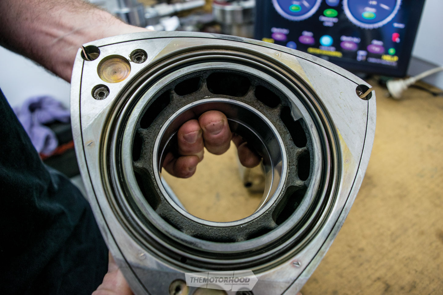
The first stage in balancing begins with the rotors themselves. Grant tells us it’s not uncommon to find a ‘matching’ pair being up to 50-80 grams out depending on the factory weight of the rotors. Modern RX-8 rotors aren’t balanced at all from factory.
The process begins by dynamically balacing the rotors. To do this, each rotor is weighted side-to-side, before statically balacing each one on a special jig. The heavier of the two rotors is then lightened by removing material evenly from the surface on the side of the rotor between the side seals and the oil-control seals.
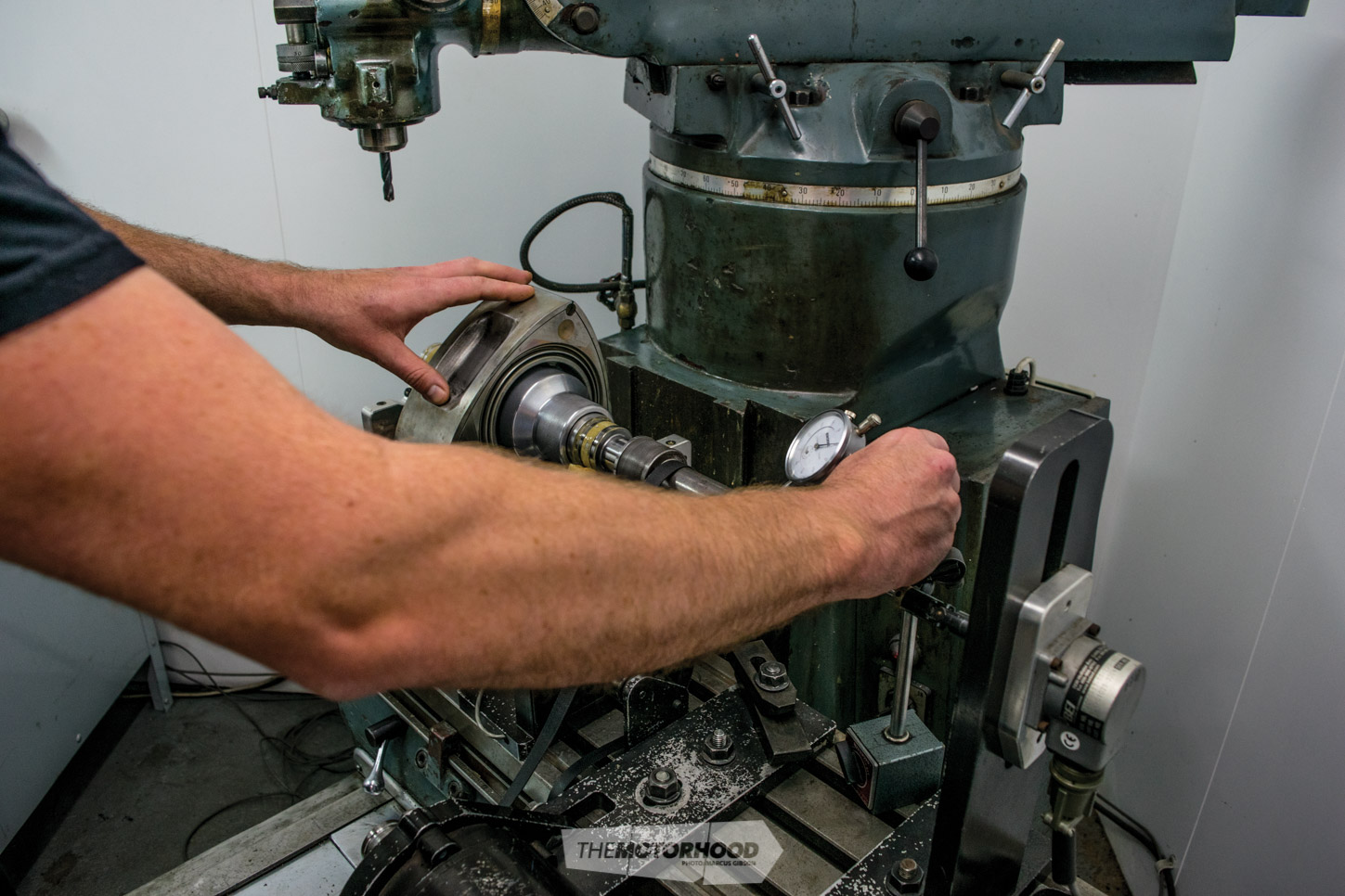
This process can be very time-consuming, as you’re constantly having to set the balancer up, then remove the rotor to machine it and, then recheck. It’s this process that soaks up the hours, especially when you’re working to Grant’s .02 tolerance
This is commonly done with a drill — hence the indents you’ll see on any rotor near each apex. The CWT balancer will tell you exactly where the material needs to be removed from in order to achieve a balanced rotor. This process can be very time-consuming, as you’re constantly having to set the balancer up, then remove the rotor to machine it, and then recheck. It’s this process that soaks up the hours, especially when you’re working to Grant’s .02g tolerance.
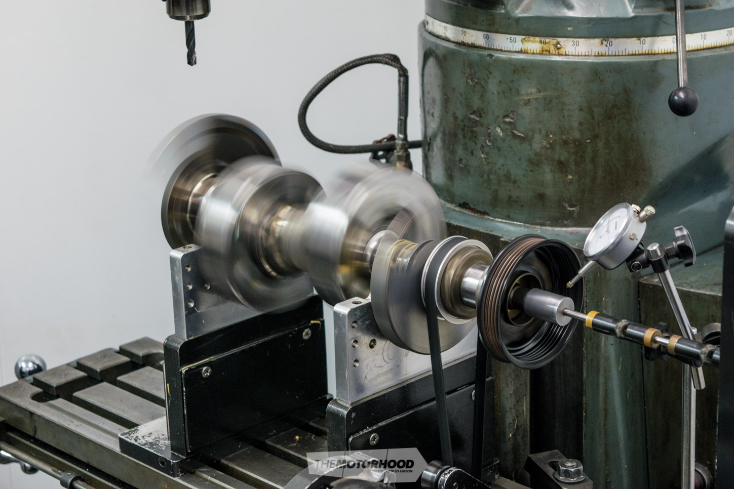
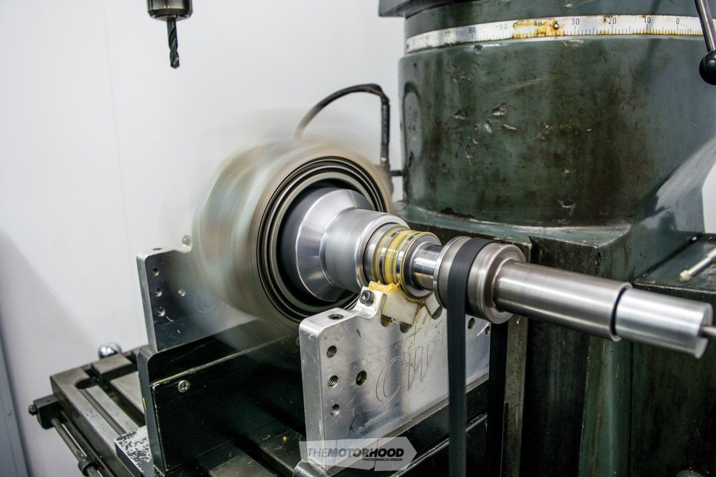
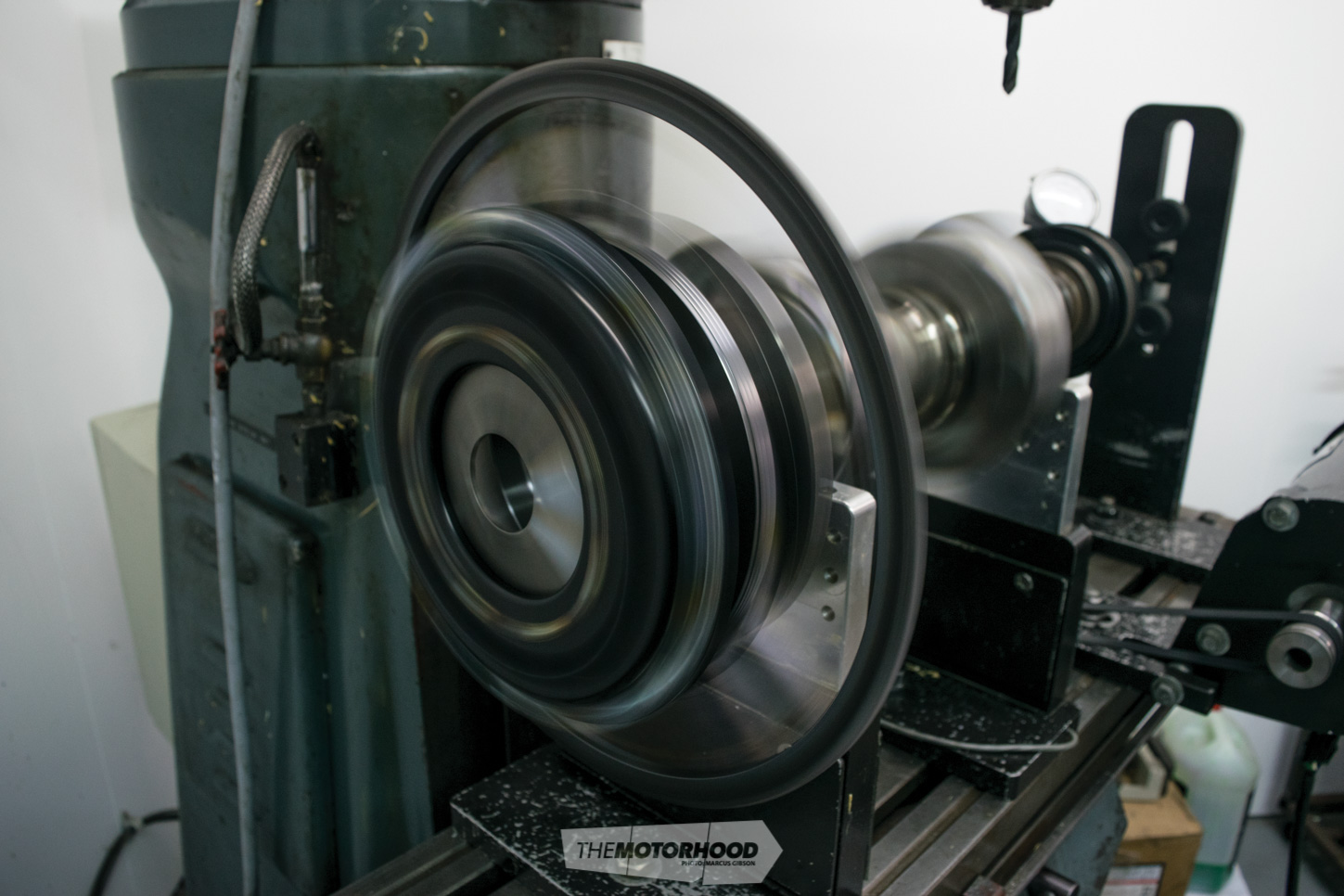
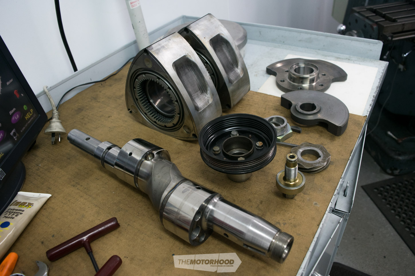
Once you have two identical rotors, the next stage is balancing the rest of the rotating assembly to suit the weight of the rotors. This is done by setting up the eccentric shaft with everything from the front pulley, to the oil-pump drive, and front and rear counterweights. The rotors themselves sit this part out, and are substituted with a pair of circular weights known as bob weights. The reason the rotors themselves are not used is because they are actually missing some of the mass that they will have once your engine is assembled and running. Each bob weight allows Grant to easily add weight to compensate for the seals, springs, and even down to things like the oil that will be inside a rotor when running. The bob weights simply slide in place and are held there by a small grub screw in the oil passage. This assembly is then spun up, and the computer calculates the weight difference between front and rear.
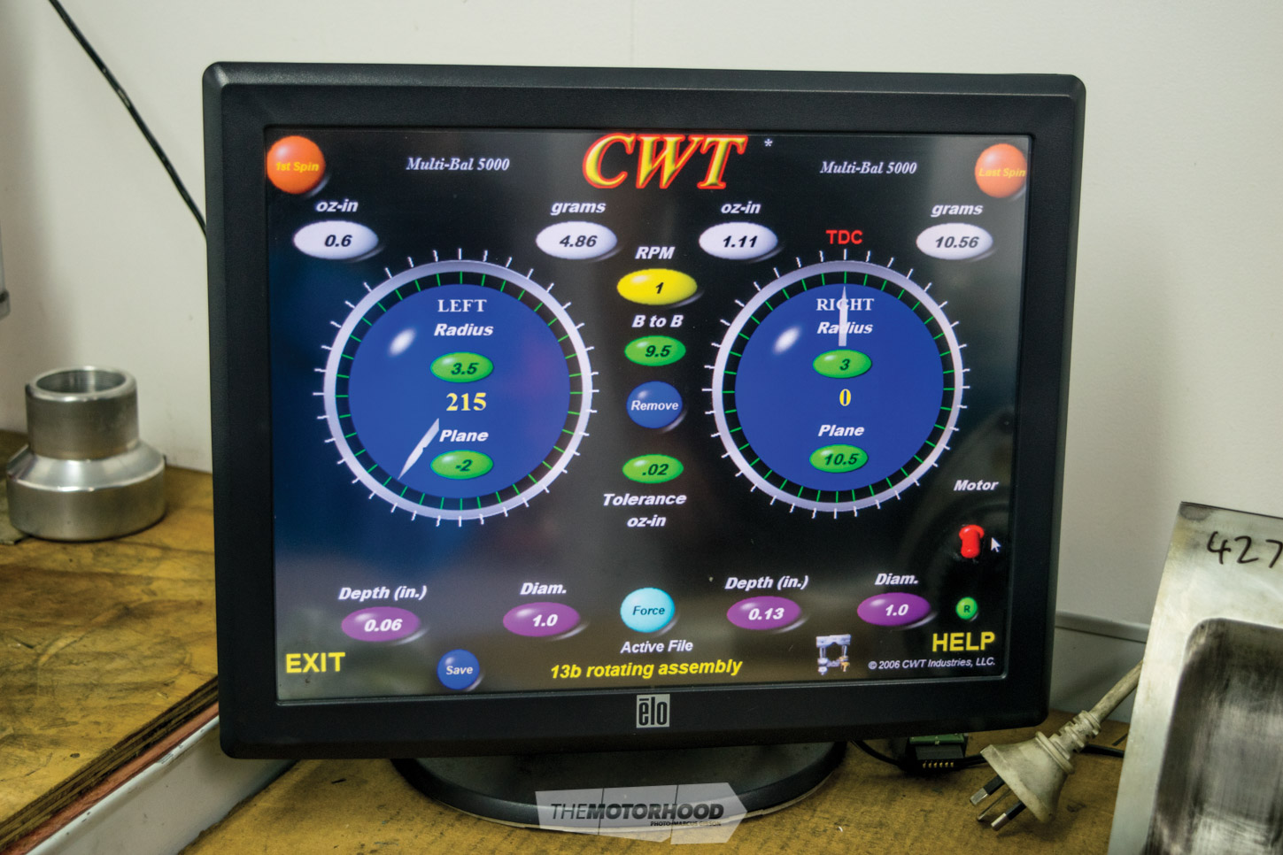
The adjustment comes from adding or removing weight from the front and rear counterweights. The front counterweight coincides with the rear rotor, and vice versa. Unlike balancing the rotors — where Grant picked the lightest and simply brought the heavier one down to suit — in this case, weight sometimes needs to be added. In the case of our 13B assembly, the balancer showed that we needed 10g added to the front.
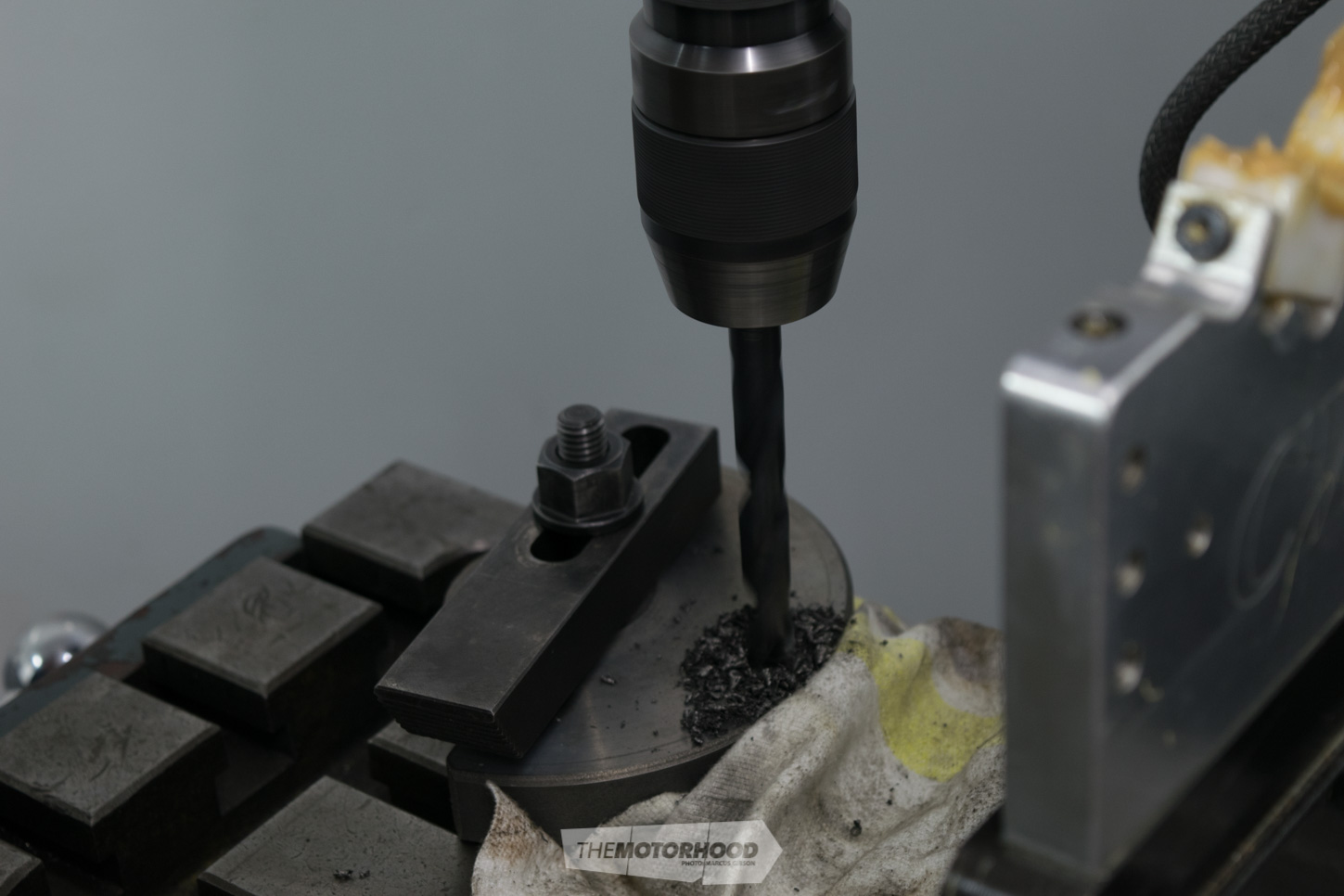
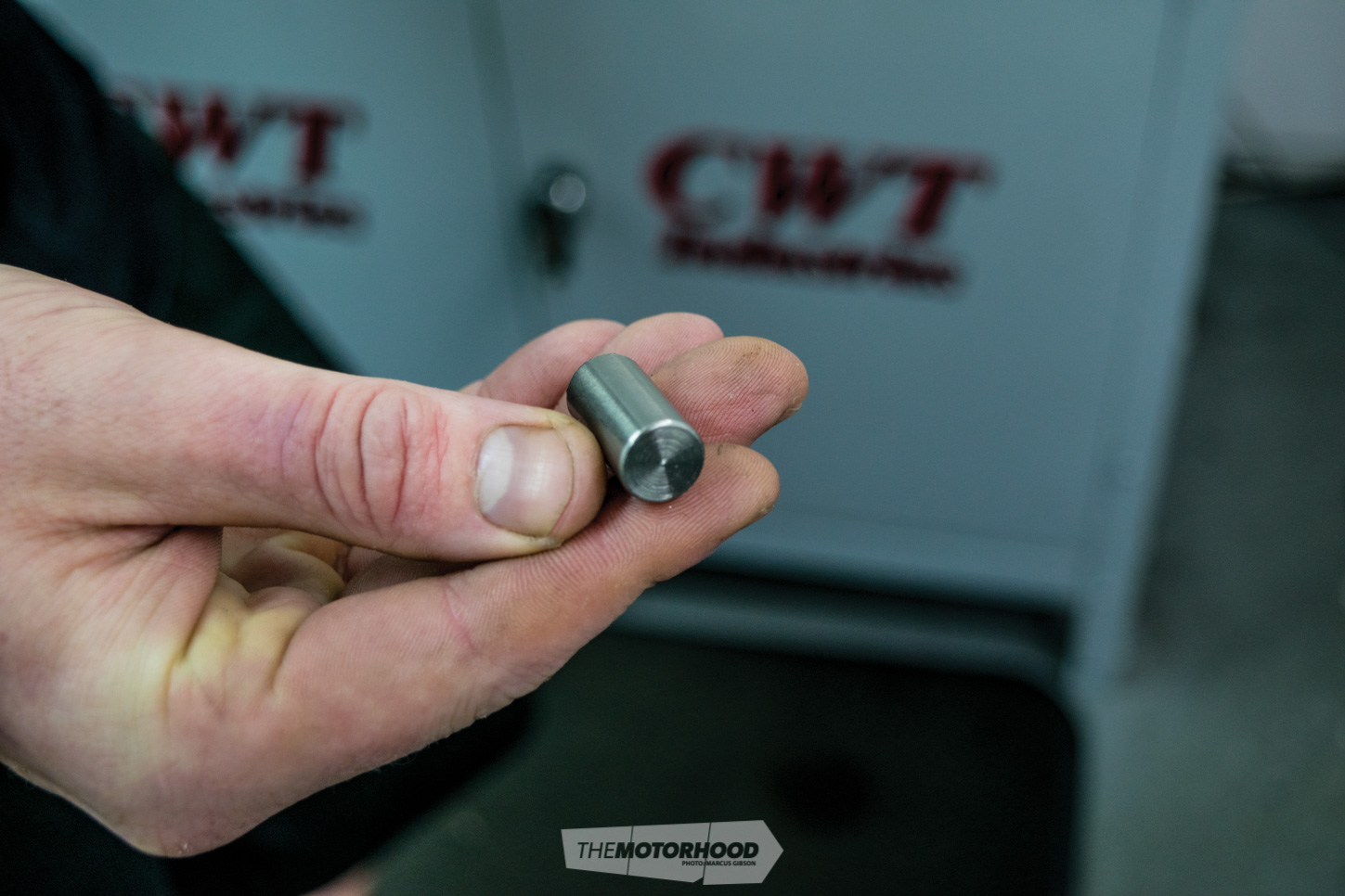
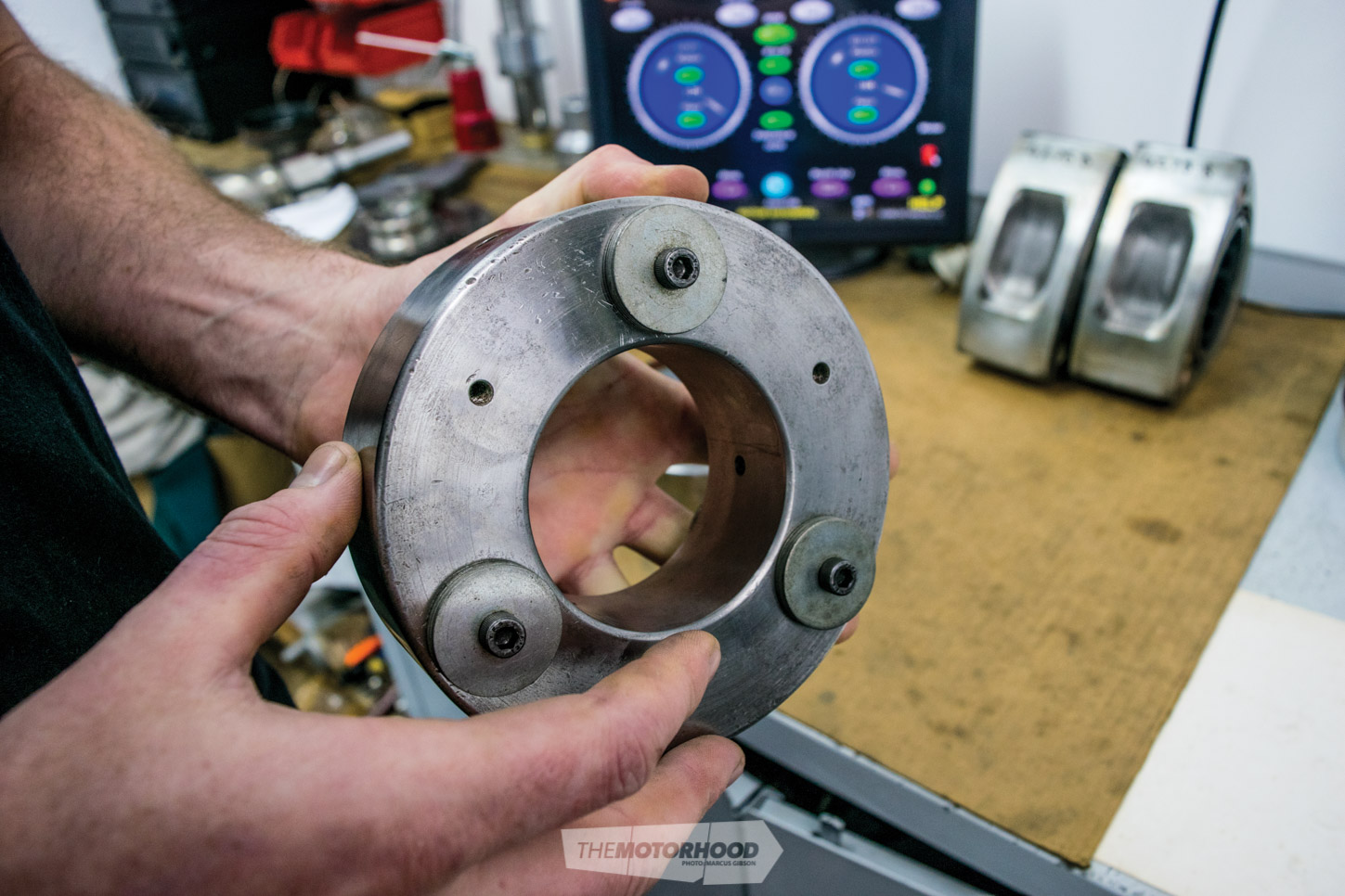
The program will tell you exactly where on the duration of the counterweight to add this. Grant uses a super-heavy metal known as Mallory, which he imports from the USA in a rod form, specific to the purpose. It weighs 50g per inch, which is twice the density of a mild-steel variant. A hole is drilled in the side of the counterweight and the Mallory slug is pressed in. As the force acting against it when the engine is running is centrifugal, there is no way the Mallory can dislodge and fire out like a bullet.
“The excess weight is removed from the outside edge, as this is the area that will have the greatest impact. The closer to the centre of the assembly, the more material you would have to remove to achieve the same result.”
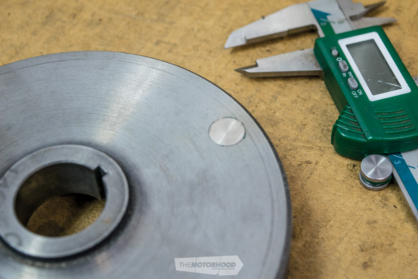
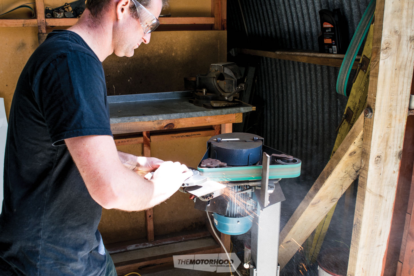
Once back on the balancer and re-spun, the rear counterweight needed a slight correction, this time to lose weight, which is a much more straightforward exercise. Grant simply sanded the edge of the counterweight at the point that the CWT had identified. Back on the balancer for a third time, it required a little more removed from a different spot. This time it was a greater amount of mass, so it was drilled from the outer edge of the counterweight. As the balancer is set up on the mill, this was done in place. The excess weight is removed from the outside edge, as this is the area that will have the greatest impact. The closer to the centre of the assembly, the more material you would have to remove to achieve the same result. We had to repeat this process a few times to bring the assembly inside the .02g tolerance Grant works to, although up to .038g is an acceptable tolerance.
The final stage was balancing the flywheel and pressure plate. We instantly jumped from .02g to 2.9g after adding these items. This time, weight is removed from the pressure plate to bring it back down, by drilling into the face. In this case, being an alloy Quarter Master, it required a fair amount of material to be removed to bring it back within tolerance.
So there you have it — the complete rotating assembly, ready for the engine builder to piece together with the knowledge that it will happily spin away at extreme rpm without fear of it tearing the engine from the mounts and destroying the internals. Yes, it’s an added cost at the engine-build stage, but if it’s not done, or worse, done incorrectly, it could cost you your engine in a very short space of time and land you a big repair bill. Do it once, do it right.
This article originally appear in NZ Performance Car issue No. 243. You can get your hands on a print copy or digital copy at the links below: